
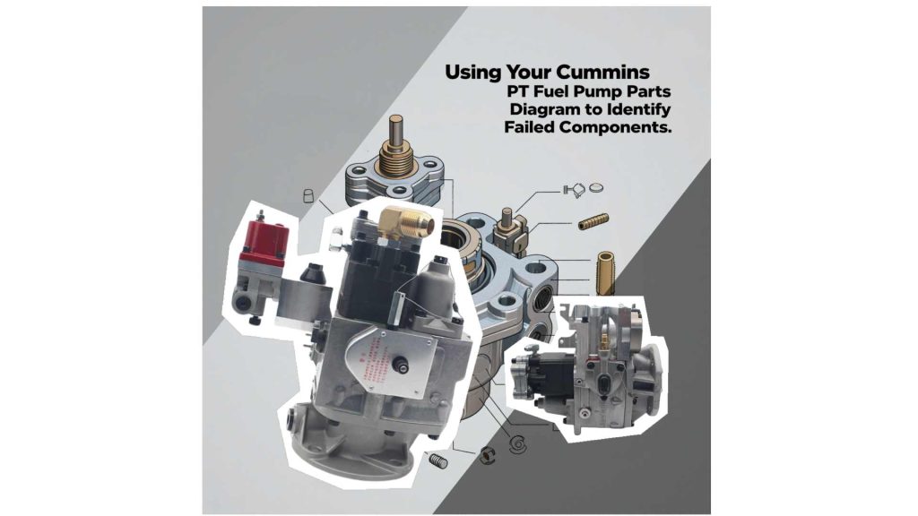
Using Your PT Fuel Pump Parts Diagram to Identify Failed Components
The mechanic is at a loss when dealing with the disassembled PT fuel pump, and the car owner encounters problems such as insufficient power and black smoke after repeated repairs without success. The fuel leakage cannot be traced to its source. The core of these predicaments lies in the fact that it is known that the PT pump is faulty, but the specific failed component cannot be identified. Blind maintenance not only leads to low efficiency but also increases costs.
In fact, the PT fuel pump parts diagram is the most direct diagnostic basis. This article will guide you to quickly locate the key components of common faults through parts diagram.
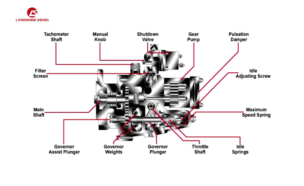
Do You Know The PT Fuel Pump Parts Diagram?
Don’t underestimate the diagram of the PT pump part in your hand. It is the key map for you to solve the case. This picture shows the positions, names, numbers and interrelationships of all the parts. Don’t be afraid it looks complicated. Next, we’ll teach you which parts to focus on!
Quickly understanding the view is the foundation. Among the main view, section view, and partial magnification view, the focus should be on the section view and magnification view, as they can expose the key internal components!
It is also necessary to learn to read key legends to quickly locate symbols and positions such as O-rings, gaskets, Bushing/Shaft, springs, and precision plungers.
The fault phenomenon is a clue pointing to a specific functional module. The functional module corresponds to the area on the part drawing, and within this area, there are key vulnerable parts. Mastering this “symptom – location – component” triangular association method can enable you to identify the problem more quickly.
Graphical Analysis And Diagnosis Of The Five Common Faults
Fault 1: Insufficient power and slow acceleration
The engine power decreases, the climbing and acceleration performance weakens, and the engine speed increases slowly when the throttle is fully open.
There might be faulty parts
The gear pump oil supply unit and the main oil circuit pressure system are often caused by insufficient oil supply or abnormal pressure.
Key component positioning
- Gear pump gears
- Gear bushings
- Main oil circuit pressure regulating valve and spring
- Oil inlet filter screen and sealing parts
Cause of malfunction
The wear of gears or shaft sleeves leads to insufficient oil pumping volume. The pressure regulator gets stuck, causing abnormal pressure. Clogging of the filter screen or failure of the seal causing air suction will both lead to insufficient fuel injection and result in a decrease in power.
Safety reminder: Pressure relief must be completed before operation
Fault 2: Black smoke is coming from the exhaust pipe
The exhaust continues to emit black smoke, which intensifies during sudden acceleration and may be accompanied by a slight decrease in power.
There might be faulty parts
The throttle valve control unit and governor system suffered from excessive fuel supply due to the loss of control of fuel metering.
Positioning of key components
- Throttle valve shaft and bushing
- VS Governor plunger/sleeve
- Governor flyhammer assembly and spring
Cause of malfunction
The wear of the throttle valve shaft leads to fuel leakage. Excessive clearance between the plunger and the sleeve causes inaccurate measurement. If the flying hammer assembly gets stuck and causes the idle fuel supply to exceed the standard, it will lead to incomplete fuel combustion and the formation of black smoke.
Safety reminder: Pressure relief must be completed before operation
Fault 3: Difficulty in starting (especially obvious when the vehicle is cold)
It takes multiple starts to succeed, and the probability of startup failure increases in the cold state.
There might be faulty parts
Oil cut-off valve control unit, oil inlet sealing system and initial oil supply component of gear pump.
Positioning of key components
- Oil cut-off valve
- Seal of the oil inlet pipe joint
- Initial wear parts of gear pumps
Cause of malfunction
The failure of the oil cut-off valve caused the oil passage to be blocked. Poor oil intake seal causes air intake. The initial wear of the gear pump leads to insufficient fuel supply, both of which will result in the inability to establish an effective fuel injection pressure at startup.
Safety Reminder: Circuit inspection requires power-off operation, and mechanical parts need to be depressurized
Fault 4: Unstable idle speed, stalling, and easy stalling
At idle speed, the rotational speed fluctuates greatly, with periodic speed rises and falls. In severe cases, the engine will stall by itself.
There might be faulty parts
The core component of the governor control system was triggered by an abnormal response to speed regulation.
Positioning of key components
- Governor idle spring
- Speed-regulating plunger/sleeve
- Flying hammer assembly and shaft sleeve
- Seal of the governor housing
Cause of malfunction
Insufficient idle spring elasticity, wear of the plunger, and jamming of the flying hammer can all lead to lag in speed regulation. The failure of the shell seal causes internal leakage, disrupts the pressure balance and leads to fluctuations in oil supply.
Safety reminder: Pressure relief must be completed before operation
Fault 5: Fuel leakage
Fuel leakage occurred on the surface of the pump body, forming continuous oil stains.
There might be faulty parts
All sealing nodes correspond to different sealing components in specific positions.
Positioning of key components
- Top cover plate sealing: cover plate gasket, bolt washer
- Shaft end seal: Shaft seal and bushing
- Joint sealing: O-ring/copper gasket
- Shell sealing: Main shell gasket
Cause of malfunction
Aging, wear or improper installation of the seal can lead to seal failure, causing leakage under the action of fuel pressure.
Safety reminder: Pressure relief must be completed before operation
Diagnostic Techniques And Precautions For PT Fuel Pumps
- Application of part numbers: Through the part numbers in the figure, replacement parts can be precisely purchased to avoid model errors.
- Compound fault detection: A single symptom may involve multiple components (for example, black smoke + weakness may be related to the throttle valve and the governor), and a coordinated inspection is required.
- Exclusion of external factors: First, confirm whether the fuel filter, fuel tank ventilation, low-pressure fuel line and electrical circuit are normal to avoid misjudgment.
- Professional operation boundaries: Precision clearance measurement, governor calibration, etc. require professional equipment. It is recommended to send for repair.
- Part drawing management: Retain the latest part drawings corresponding to the engine model (available from the official website or suppliers).
Conclusion
Mastering the parts diagram diagnosis method can achieve precise location of PT pump faults and reduce blind maintenance. When encountering a malfunction, refer to the method in this article and the part diagram for troubleshooting. Simple problems can be handled independently, and for complex situations, the direction of maintenance can also be clearly defined.